| Converter | ||
|---|---|---|
| Converters | ||
| ZigBee type | ||
| Device features | ||
| Interfaces | ||
| Converter type | ||
Converters |
Availability:  product is available product is availablePrice: Inquiries: Bonus: 
I-7242DDeviceNet / Modbus RTU Gateway, CAN bus
ICPDAS
The I-7242D is one of CAN bus products in ICP DAS. The device allows a master located on a DeviceNet network to enter into a dialogue with the slaves on a Modbus RTU network In DeviceNet network, it is a
Group 2 Only Slave device, and supports “Predefined Master/Slave Connection Set”. It is a general protocol converter operating in a way that is transparent to the user. In addition, we also provide the utility software for users to configure the I-7242D,s parameters and build the EDS file. Users can easily apply Modbus RTU devices in DeviceNet applications with the I-7242D.
DeviceNet Features
Modbus RTU Features
Utility The I-7242D Utility is help users to configure the devices, and has following features:
Usage The simple steps about how to use DNS_MRU gateway are described as follows: 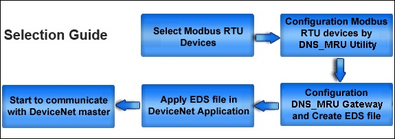
Modules Support
Similar products
 CANopen / Modbus RTU Gateway, 1x RS-232, 1x RS-485... Product features I-7232D
 Intelligent RS-232/CAN low speed fault tolerant converter... Product features I-7530-FT
 CAN/Fiber, Fiber/CAN Converter, multi mode, RoHS, RS-232... Product features I-2533CS CR
 CANopen to DCON Gateway, with 5-Segment Indicator... Product features I-7231D
 DeviceNet to DCON Gateway, with 5-Segment Indicator, CAN... Product features I-7241D
, Ethernet, device server, 100fx, multi mode") CAN/Fiber Converter (RoHS), Ethernet, device server, 100fx, multi mode... Product features I-2532
, CAN, RS-232, 100Base-TX RJ-45") DeviceNet Slave / Modbus Master Gateway (RoHS), CAN, RS-232, 100Base-TX RJ-45... Product features GW-7243D
") Modbus TCP server & Modbus RTU slave to CANopen master Gateway (RoHS)... Product features GW-7433D
 CANopen Embedded Device with 2 I/O Expansion, converter, extension module... Product features CAN-8223
 CANopen Embedded Device with 1 I/O Expansion, converter, expansion module, CPU 8... Product features CAN-8123
 Modbus/TCP server to DeviceNet master Gateway, CAN, UART, Ethernet, RS-232/485, ... Product features I-7243D
 Modbus RTU to CAN Converter, RS-232/RS-422/RS-485... Product features I-7530A-MR
 CAN to Ethernet/ Modubs TCP/ Modbus RTU Converter, 1x RS-232, 1x RS-485, 10/100B... Product features I-7540D-MTCP
, multi mode") CAN/Fiber, Fiber/CAN Converter (RoHS), multi mode... Product features CAN/Fiber, Fiber/CAN Converter, multi mode, RoHS, RS-232... Product features I-2533CS-B CR
 CAN/Fiber, Fiber/CAN Converter, multi mode, RoHS, RS-232... Product features I-2533CS-A CR
|
|||||||||||||||||||||||||||||||||||||||||||||||||||||||||||||||||||||||||||||||||||||||||||||||||||||||||||||||||||||||||||||||||||||||||||||||||||||||||||||||||||||||||||||||||||||||||||||||||||||||||||||||||||||||||||||||||||||||||||||||||||||||||||||||||||||||||||||||||||||||||||||||||||||||||||||||||||||||||||||||||||||||||||||||||||||||||||||||||||||

